Sizing a linear actuator and estimating life are done quite easily once you understand the basic needs of the application. The following is the minimum information needed to begin this process.
- Linear force needed to move the load
- Linear distance the load needs to be moved
- Time required to execute the movement
- Actuator frame sizes and physical power output tables
- Actuator force versus speed (performance) curves
- Cycles of life versus percent rated load curve
|
 Mechanical Power Requirements
The power required to meet any motion application is now calculated using the parameters. This will allow you to easily choose the correct motor frame size.
39.37” = 1 meter
1 lb force = 4.448 newtons
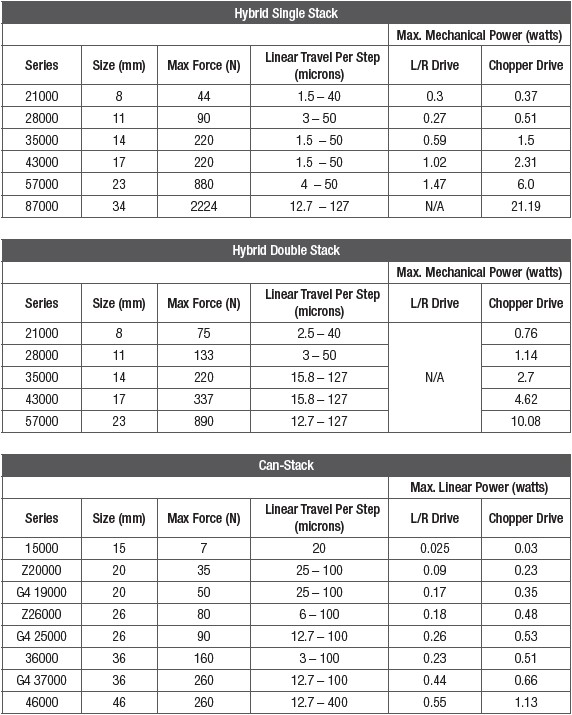
NOTE: Mechanical power than can be delivered as linear motion should not be confused with total electrical power consumed by an actuator. Both are given as watts. The values in the table (left) are less than electrical power as given in the individual motor tables (electrical specifications).
Once the power is known in watts, choose the proper frame size of the actuator as listed in Table 1. All stepper motor linear actuators require a drive to send pulses to the motor. As shown in Table 1, the power for both an L/R (constant voltage) drive and a chopper (constant current) drive is listed. Most applications today use a chopper drive. Unless the application is limited (as in a hand-held portable or battery powered device), a chopper drive is highly recommended to get maximum performance from the linear actuator. This is especially true at higher force and speed applications.
Table 1. Frame Sizes and Performance Based On Required Output Power
Velocity
After calculating the mechanical power needed to meet application requirements, the linear velocity in inches per second is calculated using the following equation.
Force versus Linear Velocity Curves
Once the required actuator frame size is determined and the linear velocity is calculated, the “force vs. linear velocity curve” is used to determine the proper resolution of the actuator lead screw. Each curve represents the maximum force that can be generated by the actuator at that speed for that specific screw, or 100% of rated load/force. It is also under the condition of going at speed from a standing start.
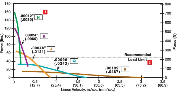 |
Figure 1: Size 17 43000 Single-Stack, 1.8° Step Angle Series Actuator, Force versus Linear Velocity.
.218 in (5.5mm) diam. Lead Screw, Bipolar, Chopper Drive, 100% Duty Cycle
Actuator Life
There are many variables that ultimately determine the life of an actuator. The best way to predict life is through application testing, which is highly recommended. There is, however, a first
approximation technique that can help estimate this value. The stepper motor prime mover contains no brushes to wear out and also utilizes precision, long life ball bearings. The main wear component is the lead screw nut interface. The number of cycles can be summarized as a function of percent rated load, as illustrated in Figure 2 below.
Figure 2: Percent Rated Load versus Number of Cycles.
NOTE: A cycle is defined as a move to full extension and return to the start point.
Example 1
COMPUTATION: Calculate the initial rated force based on required # of cycles of life (see Example 1,
Application Requirements, right)
Step 1: Refer to Figure 2 and determine the correct sizing factor needed in order for the actuator to achieve the required 1,000,000 cycles. This is illustrated with the yellow line in Figure 3 below.
Figure 3: Safety Factor Needed To Meet 1,000,000 Cycle
Step 2: As indicated in the chart, in order to get 1,000,000 cycles, a factor of 0.5 as 50% rated load must be used when sizing the actuator. The initial rated force required in order to meet the load after 1,000,000 cycles is:
Step 3: Convert lbs f to Newtons (N)
| 30 lbs / (0.225 lbs / N) = 133 N |
COMPUTATION: Determine required travel in meters
| 3 in x (0.0254 M / in) = 0.0762 M |
COMPUTATION: Choose the proper frame size actuator using the selector chart
Step 1: Determine the required linear mechanical power in watts
Step 2: Use Table 1 to determine the correct frame size actuator. As discussed earlier in the article, most applications will use a chopper drive to supply the required input pulses to the stepper motor. The 43000 (Size 17 Hybrid) was chosen for this application, as highlighted below in the Hybrid Single Stack section of Table 1, shown again below.
COMPUTATION: Determine the proper resolution using the “Force vs Linear Velocity” chart
As determined by the life calculation performed above, an initial load of 30 lbs is to be moved at a velocity of 0.5in/s. The resulting lead screw resolution required in the Size 17 hybrid motor is 0.00048” (J resolution), as indicated in Figure 4.
 |
|
 |
Figure 4: Size 17 43000 Series Actuator, Force versus Linear Velocity. .218 in (5.5mm) diam. Lead Screw, Bipolar, Chopper Drive, 100% Duty Cycle. Lead screw resolution required in the Size 17 hybrid motor is 0.00048” (J resolution), as indicated.
NOTE: Another way to approach this solution is to realize that if you require 1 million cycles of life, that the force reserve must be a factor of 2x. Simply, the force at any speed must not be higher than 50% of rated load, or no more than half way to the line (100% rated load).
COMPUTATION: Verify selection by checking force at the required step rate
Earlier in the paper, it was discussed that the lead screw advances based on the number of input steps to the motor. Haydon performance curves are expressed in both “in/sec” (as illustrated in Figure 4) and also in “steps/ sec” (Figure 5). As an effective check, verify the selection by checking the force at the required step rate. This also allows a check on motor speed to achieve the required linear motion speed for a certain resolution screw. This becomes more important when using higher resolution (finer) screws to achieve faster linear speeds as a seemingly low linear speed may correlate with a fast motor speed.
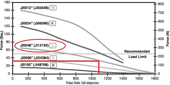 |
Figure 5: Size 17 43000 Single-Stack, 1.8° Step Angle Series Actuator, Force versus Pulse Rate. .218 in (5.5mm) diam Lead Screw, Bipolar, Chopper Drive, 100% Duty Cycle Figures 4 and 5 are good illustrations of how the pulses to the stepper motor translate into linear motion through the lead screw.
Conclusions
- Proper sizing and life estimation of an actuator is the critical first step to success in the design of all linear motion systems.
- Through the use of stepper motor based linear actuators, rotary-to-linear motion takes place inside the motor or external at the lead screw threaded engineering thermoplastic nut interface. This method offers unique advantages over alternative approaches, such as fewer components, smaller overall footprint size, high force output, and long stroke lengths in short greater mechanical efficiency. What’s more, the high precision, repeatability, long component life are especially desirable, as are the high resolutions possible.
example
- In addition, the use of the stepper motor translates to a lower overall cost for OEM equipment builders in terms of development and production. Most importantly, this method can be utilized in a variety of vertical markets, including medical, laboratory instrumentation, semiconductor, aerospace, and virtually any other application where precision linear motion is required.
|
Click here to download PDF version.