Connecting brushless DC motors to electronic motor controllers is complicated by the fact that motor phase leads and sensor leads must be connected in a precise phase configuration to the electronic motor controller for proper operation. Many times the information required determining the proper motor sensor and phase lead connection to the electronic motor controller is inaccessible, and must be obtained by measurement. This paper explains the importance of the phasing relationship between motor sensor and phase leads, and how the relationship can be measured. Finally it explains how to ensure proper connection of the motor phase and signal leads to the electronic motor controller.
 Sensor
Hall Effect sensors on brushless DC motors provide the position of the magnetic pole on the motor rotor (rotating element) relative to the motor phase coil windings on the motor stator (stationary element). The Hall Effect sensors are used to indicate which stator phase winding to energize to generate the maximum motor torque in the desired direction of rotation.
Injecting electrical current into the motor phase coils produces an electro-magnetic pole on the stator periphery, attracting the magnetic pole on the rotor, producing torque and rotation on the motor shaft. Maximum motor torque is produced by generating an electro-magnetic pole on the stator periphery spaced 90 degrees (in quadrature) with respect to the rotor magnetic pole. A rotating magnetic field on the stator periphery is obtained by energizing the motor phase coils in sequence, in essence creating a rotating electromagnet on the stator periphery. The electromagnetic pole generated on the stator periphery must rotate synchronously around the stator periphery at the same rotational velocity as the rotor magnetic pole to produce continuous torque. The rotating rotor magnetic pole synchronously chases the rotating stator magnetic pole around the stator periphery. The relative position between the rotating stator and rotor magnetic poles ideally remains fixed in a quadrature angular position, producing a maximum constant torque when both magnetic poles are rotating at the same velocity. A link to an animation of brushless DC motor operation is provided in the glossary as a graphical aid to understand this concept.
The three Hall Effect sensors are spaced equal angular distance apart to detect the location of the rotor magnetic pole relative to the three equally spaced motor phase windings (Figure 1). The three hall sensor switch states are used to indicate which motor phase coils to energize to produce maximum torque on the rotor.
|
 |
| Figure 1 Illustration of Hall Effect Sensor placement on the periphery of the motor stator to detect rotor magnetic pole position relative to the motor stator poles |
The relationship between Hall Effect switch states and optimum motor phase coils excitation can be provided in tabular form. An example is provided below in (Figure 2):
 |
| Figure 2. Table of hall sensor states and motor phase excitation to produce the maximum torque in the desired direction of rotation. |
Methods
Many different nomenclatures exist for designating the three motor phase leads on brushless DC motors. Typical nomenclatures for motor phase lead designators are [A,B,C ], [R,S,T], [ U,V,W], or [W1,W2, W3]. For the purposes of this paper the [A, B, C] labeling nomenclature will be used for motor phase lead designations. Likewise, the Hall Effect Sensor nomenclature referred to in this paper is [ H1, H2, and H3], although other typical nomenclatures are [ Hall 1, Hall 2, and Hall 3], [Hall A, B,C] or [Sensor 1, 2, 3].
The table providing the relationship between the Hall Effect sensor states, which indicates the rotor position relative to the stator phase windings, may be provided by the motor manufacturer. Section # 1 describes typical formats for this information. If this information is not accessible, then the table must be generated by measurement. A method to generate the table by measurement is provided in Section #2. Section #3 describes how to utilize the tables to properly connect the motor to the electronic motor controller.
SECTIONS:
1. Hall Based Table Information Provided
2. Using Phase Current Injection Method to
Create Motor Hall Sensor Correlation Table
3. Connecting the Motor to the Electronic Controller
4. Other Measurement Methods
Section 1: Hall Based Table Provided
This scenario is preferred since it does not require any direct motor measurement or measuring equipment, but relies on access to the brushless motor and electronic controller hall sensor correlation tables. Many brushless DC motor vendors provide information in the motor data sheet to help with ascertaining the proper motor connection sequence to the electronic controller. The brushless motor and electronic controller hall sensor correlation table is usually provided in the form of a diagram or table which may have different titles such as “Block Commutation” or “Brushless DC Motor Timing Diagram”. Typically these diagrams illustrate the motor phase voltage sequence, or alternatively the state of the motor controller motor phase power switches, correlated to the hall sensor states over one complete electrical rotational cycle. The table describes which motor phase coils to energize depending on the hall sensor switch states to provide optimum motor torque. Examples of each type of table are provided below:
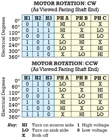 |
120° ELECTRICAL SPACING
(Waveforms with Respect to Ground) |
 |
If the motor and controller correlation diagrams are identical for both rotational directions than simply connect the motor and controller directly using the same designated nomenclature. For example, the motor phase lead designated A is connected to the electronic motor controller phase output designated A, and the motor hall sensor lead designated 1 is connected to the electronic motor controller input designated Hall sensor 1. If they do not match exactly than table manipulation is required to determine which motor phase leads must be re-designated to match the controller table. Refer to section 3, Connecting the Motor to the Electronic Control for more information.
Section 2: Phase Current Injection Measurement to Create Motor Hall Table
This method requires the following electronic equipment:
Adjustable voltage DC power supply (adjustable current limit preferred)
Volt meter to measure Hall Effect sensor signal voltage state.
This method can be used to measure the Hall Effect sensor correlation table if this information is not available. This method involves injecting a fixed DC current into the motor phase windings to create a fixed electromagnetic pole on the stator periphery, as illustrated below. The motor is placed on a bench without any load coupled to
the shaft, with the motor shaft free to rotate. When motor phase windings are energized, the rotor magnetic pole is attracted to the stator electromagnetic pole, and the rotor pole rotates to align under the motor phase winding which is injected with current and producing the electromagnetic pole on the stator periphery. The hall sensor
states are recorded for this rotor angular position. The process is repeated by injecting current into a different combination of stator phase coils, creating an electromagnetic pole at a different angular position on the stator periphery. The current from the DC power supply must be limited to the maximum motor rated continuous current to ensure no damage to the motor occurs.
 |
|
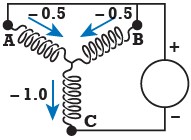 |
Connection producing a magnetic pole aligned under
the phase A winding. |
|
Connection producing a magnetic pole of reverse polarity aligned under the
phase C winding. |
The motor phase windings are energized in a sequence that rotates the stator electromagnetic pole sequentially around the stator periphery, producing sequential rotation of the rotor. Hall sensor states and shaft direction of rotation are recorded at each excitation sequence, creating a mapped correlation table.

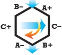
The derived table must be manipulated for motor controllers using six step (block) commutation. The phase excitation sequence in the table produces a magnetic pole on the stator periphery which is aligned with the rotor magnetic pole. The hall sensors indicate the position of the rotor magnetic pole aligned under the energized phase. The actual phase excitation sequence must produce a magnetic pole on the stator periphery spaced in quadrature to the rotor magnetic pole to produce torque. The six step (block) commutation method only energizes two phases at a time. The off phase is the phase that the rotor is aligned under, and the remaining phases produce the electromagnet pole on the stator periphery in quadrature with the rotor magnetic pole position. Mark an x indicating the off phase for each row of the table which has single polarity.
 |
The magnetic pole generated on the stator periphery, which is in quadrature to the rotor pole, can be placed either +/-90 degree from the rotor magnetic pole by controlling the polarity of the injected phase currents on the two phases. The location of the magnetic pole generated on the stator periphery relative to the rotor magnetic pole determines the direction of rotation which torque is applied on the rotor. Therefore flipping the polarity of the two energized phases will apply torque in the opposite rotation of direction.
 |
|
|
Magnetic pole generated
on the stator periphery
positioned in alignment
with the rotor magnetic
pole when three stator
coils are energized
according to the diagram |
|
 |
| |
|
|
|
|
|
 |
|
|
Magnetic pole on the
stator periphery positioned
in quadrature with the rotor
magnetic pole to produce
counter clockwise rotation
when two stator coils are
energized according to
the diagram |
|
 |
| |
|
|
|
|
|
 |
|
|
Magnetic pole on stator
periphery positioned in
quadrature with the rotor
magnetic pole to produce
clockwise rotation when
two stator coils are
energized according to
the diagram below: |
|
 |
The motor phase sequence to energize to produce counter clockwise rotation at a given rotor position provided by the hall sensor states is provided below:

The sequence is flipped for counter clock wise rotation:

The resulting table correlating motor phase excitation to hall sensor state is illustrated below:

Section 3: Connecting the Motor to the Electronic Control
Illustrated below are example Hall Effect sensor tables for an electronic controller and a motor.

The first step is to adjust table rows until the hall sensor portion of the tables are identical:

The second step is to swap positions of the motor phase designator columns until the tables match:

Re-designate the motor phase leads to match the controller table:

The motor and controller correlation diagrams are now identical. Simply connect the motor and controller directly using the same designated nomenclature. For example, the motor phase lead designated A is connected to the electronic motor controller phase output designated A, and the motor hall sensor lead designated 1 is connected to the electronic motor controller input designated Hall sensor 1.
Section 4: Other Methods
BEMF Diagram
This method requires the following equipment:
4 channel oscilloscope
A method to mechanically drive the BLDC motor safely under the BLDC motors rated maximum speed
This method involves mechanically driving the BLDC motor to operate as a generator. The generated phase A to phase B voltage produced by the motor is monitored on one channel of the oscilloscope, and the three Hall Effect sensor voltage states are monitored on the remaining three channels of the oscilloscope. The correlation of the generated motor phase voltages and the Hall Effect sensor states provide the motor phase rotor position relationship.
Connection by Trial and Error
The trial and error method involves trying all possible motor Hall Effect sensor connection combinations to the electronic drive until the optimal configuration is found. Unfortunately combinations exist which may operate the motor in a very inefficient mode. For this reason it may be difficult to ascertain the optimal hall sensor connection combination, so therefore this method is not recommended.
Many electronic controls contain features which assist in ensuring correct motor connection to the electronic controller. An example is the PC fully programmable IDEA Drive from AMETEK Precision Motion Control, which provides graphical information of motor phasing and Hall Effect sensor states. Click here to find more information about Pittman PC programmable IDEA Drive.
Click here to download PDF version.